Material Testing
Transformation Point Measurement Test (Formaster Test)
In-page menu
JFE-TEC provides measurement of transformation point.
Do you have any problems with determination of heat treatment conditions?
Transformation point can be measured by giving temperature history of heating/cooling to specimen mounted in Formaster equipment. Transformation point can be detected from infinitesimal displacement due to expansion and contraction of test specimen.
We can measure general thermal expansion, etc. of materials, and transformation characteristics (crystal structure change/microstructure change by the effect of composition and thermal history) by Formaster equipment.
For example, transformation characteristics of steel materials are shown by using TTT diagram (time-temperature-transformation diagram), CCT diagram (continuous cooling transformation phase diagram) or TTA diagram (time temperature austenitization diagram), etc.
Use of simulated results of thermal history received during heat treatment process also helps study optimization of heat treatment conditions (heating rate, holding time, cooling rate, cooling stop temperature, etc.) for actual manufacturing processes necessary for obtaining intended product quality (hardness, microstructure, etc.).
Outline of Formaster Testing
Transformation point can be detected by measuring thermal expansion/contraction or expansion/contraction due to transformation of test specimen during heating or cooling in Formaster testing. The feature of the equipment is to be able to select heating/cooling rate freely by using high-frequency induction heating and inert gas cooling systems.
It is also possible to measure transformation point or observe microstructures after heat treatment by simulating actual heat treatment process.
Features of Formaster Equipment
-
- Heating performance
- Cooling performance
- Test piece
Heating method :High-frequency induction heating
Atmosphere :Vacuum or inert gas (N2, Ar, He)
Heating temperature :R.T. to 1,600℃
Heating rate :Max. 200℃/sCooling method :N2/He gas cooling
Cooling rate :Max. 100℃/sStandard :φ3 × 10 mm
Flat shape :0.7 - 2.5 mm (thickness) × 3 mm (width) × 10 mm (length) -

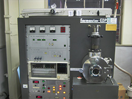
Formaster equipment
(by Fuji Electronic Industrial Co., Ltd.)
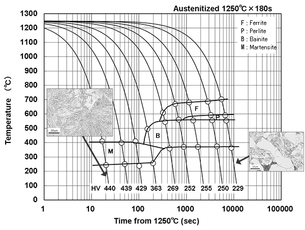
CCT diagram of alloy steel
Example of CCT diagram for high-C alloy steel. After heating to 1,250℃, test piece was continuously cooled at the cooling rate of 0.1-50℃/s, transformation point was detected, and the type of transformation was determined by microstructure observation and hardness measurement after cooling.

Evaluation of transformation behavior of hot pressed material
-
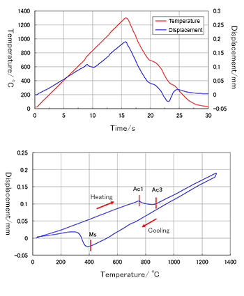
Hot press forming is a method to create shape and strength of steel sheet at the same time by combining heat treatment with press forming. Thin steel sheet with thickness less than 1 mm can sometimes be used in hot press forming. In that case, standard size of the test piece (φ3 × 12 mm) cannot be sampled. JFE-TEC succeeded to apply Formaster equipment to thinner materials even with 0.7 mm in thickness to study transformation behavior during hot press forming.
-

Transformation behavior of steel sheet of 0.8 mm in thickness during hot press forming
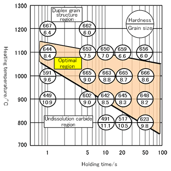
TTA diagram of alloy steel
-
One of critical factors of heat treatment, such as quenching of steel materials, is austenitization condition by heating. If austenitization is insufficient, intended strength cannot be obtained due to undissolution of carbides.
Conversely, excessive austenitization forms duplex grain structure in austenite grains, impairing homogeneity after quenching.
Transformation point Ac1, which is a temperature where material changes from ferrite to austenite structure, during heating increases with the increase of heating rate. As heat treatment by high-frequency heating or conductive-type resistance heating gives higher heating rate, it is important to determine austenitization conditions.
Microstructures, hardness and austenite grain size can be measured by changing heating rate, heating temperature and holding time under Formaster testing. Austenitization diagram is a diagram to show optimum austenitization conditions obtained from those results.
-

Time temperature austenitization diagram (TTA diagram)(S50C, heating rate: 100℃/s)


